



Hydraulic hoses have become a staple of many businesses that rely on heavy machinery or equipment. Their ingenious design allows them to transfer hydraulic fluid between different parts of a machine, even under extreme temperatures or high pressure, which has made them an essential component of many industrial processes.
In this article, we will cover everything you need to know about hydraulic hoses. So, keep reading to find out more…
What is a hydraulic hose?
A hydraulic pipe is a conduit that transfers hydraulic fluid between components in order to make them operate. They play an essential role in a hydraulic system and are designed to be flexible and capable of stretching over long distances.
In order to create a consistent and reliable flow whilst protecting the hose, a hydraulic hose is made up of three layers; the outer layer, the reinforcement layer, and the inner tube.
Designed to protect the innards of the hydraulic hose, the outer layer is created from rigid materials, making it resistant to water, oil, and weather conditions.
The reinforcement layer has multiple sheaths made of coil or braided wire and is designed to protect the inner tube from tears or damage.
In order to allow the passing of fluid, the inner tube is commonly built from synthetic rubber, thermoplastics and Teflon (PTFE). This grants it a free-flowing elasticity and pressure-resistant bearing, whilst also being compatible with the fluid it carries.
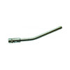
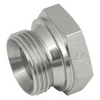
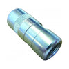
Hydraulic fittings are attached to either end of the hose to create a tight seal and prevent the risk of leaking.

What are the different types of hydraulic hose?
Hydraulic hoses are split into two different categories, which are determined by country standards: the Society of Automotive Engineers (SAE) and the European Norm (EN).
SAE hoses are widely considered to be the industry standard and are commonly used in the UK. SAE hoses can be split down into 16 categories, each denoting specific performance characteristics that are designed to meet certain temperature and pressure requirements. You can see these categories in the chart below:
|
Category |
Type |
Pressure level |
Temperature range |
Suited for |
|
SAE 100R1 |
Single steel wire braid hose |
Medium |
-40° to 100°C |
Hydraulic lines |
|
SAE 100R2 |
Double wire braid hose |
High |
-40° to 100°C |
Hydraulic oil lines |
|
SAE 100R3 |
Textile braid hose |
Low |
-40° to 100°C |
Hydraulic oil, fuel, and water-glycol |
|
SAE 100R4 |
Suction and return line |
Low |
-40° to 100°C |
Hydraulic applications |
|
SAE 100R5 |
Textile-covered single wire braid hose |
Medium |
-40° to 100°C |
Hydraulic & pneumatic applications |
|
SAE 100R6 |
Single-textile braid hose |
Low |
-40° to 100°C |
Hydraulic oil, petroleum, and water |
|
SAE 100R7 |
Thermoplastic hose with synthetic fibre reinforcement |
Medium |
-40° to 93°C |
Hydraulic & pneumatic systems |
|
SAE 100R8 |
Thermoplastic hose with synthetic fibre reinforcement |
High |
-40° to 93°C |
Hydraulic systems |
|
SAE 100R9 |
Four-spiral wire hose |
High |
-40° to 100°C |
Hydraulic systems |
|
SAE 100R10 |
Four-spiral wire hose |
High |
-40° to 100°C |
High-impulse hydraulic systems |
|
SAE 100R11 |
Six-spiral wire hose |
Extremely high |
-40° to 100°C |
Hydraulic applications |
|
SAE 100R12 |
Four-spiral wire hose |
High |
-40° to 121°C |
Hydraulic oil systems |
|
SAE 100R13 |
Multi-spiral wire hose |
Very High |
-40° to 121°C |
Hydraulic applications |
|
SAE 100R14 |
PTFE-lined, stainless steel wire-reinforced hose |
High |
-54° to 204°C |
Hydraulic applications |
|
SAE 100R15 |
Six-spiral wire hose |
Extremely high |
-40° to 121°C |
Hydraulic systems |
|
SAE 100R16 |
Compact, two-wire braid hose |
High |
-40° to 100°C |
Hydraulic applications |
What's the difference between wire braid and spiral hose?
Hydraulic hose reinforcement is built in one of two ways, and which one a hose uses decides its pressure rating, its bend radius, and which standard it falls under.
Wire braid wraps steel wire around the inner tube in a criss-cross pattern. A single braid layer suits lower-pressure work, and adding a second layer roughly doubles the working pressure at the same bore. Braided hose also bends more tightly than spiral hose of the same bore, so it suits applications where the hose has to route around other components rather than run in a straight line.
Spiral reinforcement wraps wire in continuous layers, stacked rather than woven. This holds up better under sustained high pressure and repeated pressure cycling, which is why spiral hose is used on high-pressure, high-impulse circuits such as excavator booms and breaker lines. It needs a wider bend radius than a braided hose of the same bore. Bend it tighter than its rated minimum, and the reinforcement will be damaged even if nothing shows on the outside straight away.
Neither construction is better across the board. Tight routing at moderate pressure calls for braid. Sustained high pressure with impulse cycling calls for a spiral.
What is an EN 853 hose?
EN 853 is the European standard for wire braid hydraulic hose and covers two types.
EN 853 1SN has a single wire braid layer. Typical working pressure runs from around 225 bar at a 1/4" bore down to around 88 bar at 1" bore, rated -40°C to 100°C continuous (short peaks to around 121°C are tolerated). It's the direct equivalent of SAE 100 R1AT.
EN 853 2SN adds a second braid layer, taking working pressure to around 400 bar at 1/4" bore down to around 165 bar at 1" bore. It's the equivalent of SAE 100 R2AT.
These figures are typical values from published manufacturer datasheets and vary slightly by manufacturer, so check the datasheet for your specific hose and bore size before ordering. EN 853 hose is commonly used on agricultural and mobile machinery and in general hydraulic circuits where the hose has to route around other components.
What is an EN 856 hose?
EN 856 is the European standard for spiral wire hydraulic hose, built for higher pressure and higher impulse cycling than EN 853.
EN 856 4SP has four spiral wire layers, typically rated between around 350 and 450 bar depending on bore size. EN 856 4SH adds further reinforcement again, typically rated around 420 bar at 3/4" and 1" bore, and is generally only manufactured from around 3/4" bore upwards.
Both types are rated -40°C to 100°C continuous, with short peaks tolerated to around 125°C, and both need a wider bend radius than the EN 853 types at the same bore.
Unlike EN 853, there isn't one agreed SAE 100R equivalent for EN 856 hose across all manufacturers. Treat any SAE crossover you see quoted for 4SP or 4SH as approximate, not a fixed match.
How do I read a hydraulic hose pressure rating?
A pressure rating isn't a single number; it's three.
Working pressure is the maximum pressure the hose is designed to run at continuously for its full service life. This is the figure to specify against.
Burst pressure is the pressure at which the hose is expected to fail in testing, typically around four times the working pressure. That's the built-in safety factor for pressure spikes, not a margin to design into.
Pressure rating also drops as bore size increases, even on the same hose type. A 1/2" bore EN 853 2SN hose is rated around 275 bar. A 1" bore hose of the same 2SN construction is rated around 165 bar. Don't assume a rating carries across bore sizes.
How do I choose hydraulic hose fittings?
There are six main types of hydraulic pipe fittings: BSPP, BSPT, UN/UNF, NPT/NPTF, Metric Parallel, and Metric Tapered. We've covered how to identify and choose between them in full in our dedicated guide, BSP, JIC, ORFS and Metric: Hydraulic End-Fitting Standards Compared.
Check the product specifications of your hydraulic hose to ensure that it is compatible with your chosen hose fitting.
Shop Hydraulic Values and Swivel Joints ➔
How do I know what type of hydraulic hose I need?
To determine what type of hydraulic hoses you require, you can use the acronym STAMPED. Let's break that down:
Size
There are several dimensions you need to consider when selecting a hydraulic hose.
- Length: this should be the distance between the machine parts it intends to connect. If these components move when in use, ensure that the hose doesn’t pinch or stretch too far, as this may cause the machine to malfunction. If you are replacing a hose, make sure to measure the original length before you discard it.
- Diameter: measure both the outside and inside diameters of the hose precisely. Ensure that it will connect to the required fittings. If you need to measure these diameters, you should use a precision-engineered calliper.
With both of these dimensions, note that when the hose contains pressurised hydraulic fluid, it can expand up to approximately 4% of the original size.
Temperature
Most hydraulic hoses have a maximum fluid temperature allowance between the range of 93° to 150° Celsius. Reaching or exceeding these limits can drastically reduce the lifespan of your hose, which can be accelerated if hydraulic oil with an incorrect viscosity is used.
Application
Consider how the hose will be used. The design of the hydraulic hose allows for some bending, but exceeding this bend radius will damage the reinforcement of the hose and reduce its lifespan.
Where possible, align hydraulic lines in parallel with connectors to reduce the line length and likelihood of damage to the hose.
Materials
Consult a compatibility chart before committing to a hydraulic hose type to ensure it is compatible with the fluid used. This chart should help give a general understanding, but ensure that you consult specific manufacturer guidelines before committing to a purchase:
|
Nitrile (NBR) |
EPDM |
Viton (FKM) |
Urethane (AU) |
Rubber (Natural) |
|
|
Mineral Oil |
Excellent |
Not advised |
Excellent |
Good |
Not advised |
|
Synthetic Oil |
Good |
Not advised |
Excellent |
Good |
Not advised |
|
Water-Glycol |
Good |
Excellent |
Not advised |
Excellent |
Average |
|
Phosphate Ester |
Not advised |
Excellent |
Excellent |
Average |
Not advised |
|
Biodegradable Oil |
Good |
Good |
Good |
Good |
Average |
|
Air |
Good |
Excellent |
Not advised |
Good |
Excellent |
|
Diesel Fuel |
Excellent |
Not advised |
Excellent |
Good |
Not advised |
|
Brake Fluid |
Not advised |
Excellent |
Not advised |
Good |
Not advised |
Pressure
Depending on the pressure capabilities outlined in the hose type table earlier in this article, it's important to note that the hydraulic hose selected must have a working pressure limit that is equal to or greater than the maximum system pressure. This must account for the possibility of pressure spikes, as any spikes that exceed this maximum pressure limit will significantly damage the hose and reduce its lifespan.
Ends
When selecting hose ends, they must be compatible with the hydraulic hose selected. There are two categories of coupling that connect to most host types: permanent and field-attachable.
Permanent couplings are attached to machinery via a process called cold-forming. This low-cost method is available for most rubber or thermoplastic hoses and offers a wide array of dependable connections.
Field-attachable couplings allow for attachments to be made with portable machines. They come as screw-together or clamp-type attachments which connect to the outer layer of the hose. Screw couplings attach to the hose by turning the coupling shell over the outer layer of the hose. Clamp attachments have an outer shell that connects with hydraulic hose clamps and are held in place with bolts or nuts.
Delivery
The last step of the STAMPED decision process is delivery, in which it is important to consider the availability of the chosen hose. Consider a range of preferable options to remove the worry of long delays or unavailability due to short supply.
Fulfil all your hydraulic hose needs with The Hosemaster.
We have a wide range of hydraulic hose parts and fittings to choose from to suit your needs. If you have more questions, you can contact us online, or call 01282 604 002 to speak to one of our friendly members of staff.
Find hydraulic pipe parts online today ➔
For more information, advice, and useful product buying guides, check out The Hosemaster blog
A Guide to Bend Radius For Hoses | How to Identify a Thread | How to Tell If Your Hydraulic Hose Needs Replacing
References:


